Calico over IP fabrics
Calico provides an end-to-end IP network that interconnects the endpoints (note 1) in a scale-out or cloud environment. To do that, it needs an interconnect fabric to provide the physical networking layer on which Calico operates (note 2).
Although Calico is designed to work with any underlying interconnect fabric that can support IP traffic, the fabric that has the least considerations attached to its implementation is an Ethernet fabric as discussed in Calico over Ethernet fabrics.
In most cases, the Ethernet fabric is the appropriate choice, but there are infrastructures where L3 (an IP fabric) has already been deployed, or will be deployed, and it makes sense for Calico to operate in those environments.
However, because Calico is, itself, a routed infrastructure, there are more engineering, architecture, and operations considerations that have to be weighed when running Calico with an IP routed interconnection fabric. We will briefly outline those in the rest of this post. That said, Calico operates equally well with Ethernet or IP interconnect fabrics.
Background
Basic Calico architecture overview
A description of the Calico architecture can be found in our architectural overview. However, a brief discussion of the routing and data paths is useful for the discussion.
In a Calico network, each compute server acts as a router for all of the endpoints that are hosted on that compute server. We call that function a vRouter. The data path is provided by the Linux kernel, the control plane by a BGP protocol server, and management plane by Calico's on-server agent, Felix.
Each endpoint can only communicate through its local vRouter, and the first and last hop in any Calico packet flow is an IP router hop through a vRouter. Each vRouter announces all of the endpoints it is attached to all the other vRouters and other routers on the infrastructure fabric, using BGP, usually with BGP route reflectors to increase scale. A discussion of why we use BGP can be found in Why BGP?.
Access control lists (ACLs) enforce security (and other) policy as directed by whatever cloud orchestrator is in use. There are other components in the Calico architecture, but they are irrelevant to the interconnect network fabric discussion.
Overview of current common IP scale-out fabric architectures
There are two approaches to building an IP fabric for a scale-out infrastructure. However, all of them, to date, have assumed that the edge router in the infrastructure is the top of rack (TOR) switch. In the Calico model, that function is pushed to the compute server itself.
The two approaches are:
Routing infrastructure is based on some form of IGP
Due to the limitations in scale of IGP networks, the Calico team does not believe that using an IGP to distribute endpoint reachability information will adequately scale in a Calico environment. However, it is possible to use a combination of IGP and BGP in the interconnect fabric, where an IGP communicates the path to the next-hop router (in Calico, this is often the destination compute server) and BGP is used to distribute the actual next-hop for a given endpoint. This is a valid model, and, in fact is the most common approach in a widely distributed IP network (say a carrier's backbone network). The design of these networks is somewhat complex though, and will not be addressed further in this article. (note 3).
Routing infrastructure is based entirely on BGP
In this model, the IP network is "tight enough" or has a small enough diameter that BGP can be used to distribute endpoint routes, and the paths to the next-hops for those routes is known to all of the routers in the network (in a Calico network this includes the compute servers). This is the network model that this note will address.
In this article, we will cover the second option because it is more common in the scale-out world.
BGP-only interconnect fabrics
There are multiple methods to build a BGP-only interconnect fabric. We will focus on three models, each with two widely viable variations. There are other options, and we will briefly touch on why we didn't include some of them in Other Options.
The two methods are:
-
A BGP fabric where each of the TOR switches (and their subsidiary compute servers) are a unique Autonomous System (AS) and they are interconnected via either an Ethernet switching plane provided by the spine switches in a leaf/spine architecture, or via a set of spine switches, each of which is also a unique AS. We'll refer to this as the AS per rack model. This model is detailed in IETF RFC 7938.
-
A BGP fabric where each of the compute servers is a unique AS, and the TOR switches make up a transit AS. We'll refer to this as the AS per server model.
Each of these models can either have an Ethernet or IP spine. In the case of an Ethernet spine, each spine switch provides an isolated Ethernet connection plane as in the Calico Ethernet interconnect fabric model and each TOR switch is connected to each spine switch.
Another model is where each spine switch is a unique AS, and each TOR switch BGP peers with each spine switch. In both cases, the TOR switches use ECMP to load-balance traffic between all available spine switches.
BGP network design considerations
Contrary to popular opinion, BGP is actually a fairly simple protocol. For example, the BGP configuration on a Calico compute server is approximately sixty lines long, not counting comments. The perceived complexity is due to the things that you can do with BGP. Many uses of BGP involve complex policy rules, where the behavior of BGP can be modified to meet technical (or business, financial, political, etc.) requirements. A default Calico network does not venture into those areas, (note 4) and therefore is fairly straight forward.
That said, there are a few design rules for BGP that need to be kept in mind when designing an IP fabric that will interconnect nodes in a Calico network. These BGP design requirements can be worked around, if necessary, but doing so takes the designer out of the standard BGP envelope and should only be done by an implementer who is very comfortable with advanced BGP design.
These considerations are:
-
AS continuity or AS puddling
Any router in an AS must be able to communicate with any other router in that same AS without transiting another AS.
-
Next hop behavior
By default BGP routers do not change the next hop of a route if it is peering with another router in its same AS. The inverse is also true, a BGP router will set itself as the next hop of a route if it is peering with a router in another AS.
-
Route reflection
All BGP routers in a given AS must peer with all the other routers in that AS. This is referred to a complete BGP mesh. This can become problematic as the number of routers in the AS scales up. The use of route reflectors reduce the need for the complete BGP mesh. However, route reflectors also have scaling considerations.
-
Endpoints
In a Calico network, each endpoint is a route. Hardware networking platforms are constrained by the number of routes they can learn. This is usually in range of 10,000's or 100,000's of routes. Route aggregation can help, but that is usually dependent on the capabilities of the scheduler used by the orchestration software (e.g. OpenStack).
A deeper discussion of these considerations can be found in the IP Fabric Design Considerations.
The designs discussed below address these considerations.
The AS Per Rack model
This model is the closest to the model suggested by IETF RFC 7938.
As mentioned earlier, there are two versions of this model, one with an set of Ethernet planes interconnecting the ToR switches, and the other where the core planes are also routers. The following diagrams may be useful for the discussion.
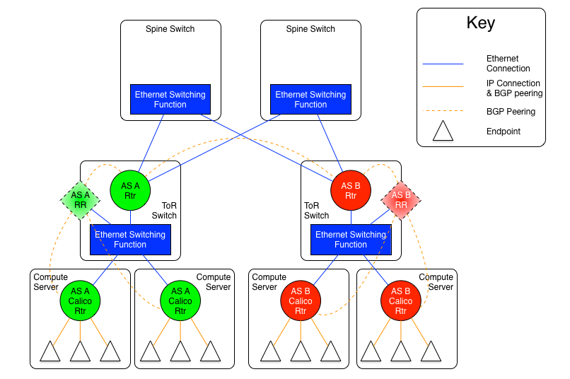
The diagram above shows the AS per rack model where the ToR switches are physically meshed via a set of Ethernet switching planes.
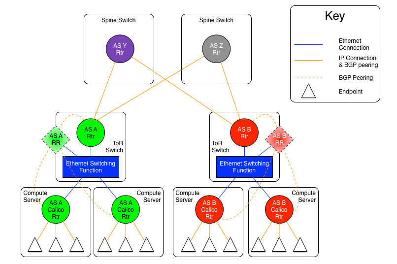
The diagram above shows the AS per rack model where the ToR switches are physically meshed via a set of discrete BGP spine routers, each in their own AS.
In this approach, every ToR-ToR or ToR-Spine (in the case of an AS per spine) link is an eBGP peering which means that there is no route-reflection possible (using standard BGP route reflectors) north of the ToR switches.
If the L2 spine option is used, the result of this is that each ToR must either peer with every other ToR switch in the cluster (which could be hundreds of peers).
If the AS per spine option is used, then each ToR only has to peer with each spine (there are usually somewhere between two and sixteen spine switches in a pod). However, the spine switches must peer with all ToR switches (again, that would be hundreds, but most spine switches have more control plane capacity than the average ToR, so this might be more scalable in many circumstances).
Within the rack, the configuration is the same for both variants, and is somewhat different than the configuration north of the ToR.
Every router within the rack, which, in the case of Calico is every compute server, shares the same AS as the ToR that they are connected to. That connection is in the form of an Ethernet switching layer. Each router in the rack must be directly connected to enable the AS to remain contiguous. The ToR's router function is then connected to that Ethernet switching layer as well. The actual configuration of this is dependent on the ToR in use, but usually it means that the ports that are connected to the compute servers are treated as subnet or segment ports, and then the ToR's router function has a single interface into that subnet.
This configuration allows each compute server to connect to each other compute server in the rack without going through the ToR router, but it will, of course, go through the ToR switching function. The compute servers and the ToR router could all be directly meshed, or a route reflector could be used within the rack, either hosted on the ToR itself, or as a virtual function hosted on one or more compute servers within the rack.
The ToR, as the eBGP router redistributes all of the routes from other ToRs as well as routes external to the data center to the compute servers that are in its AS, and announces all of the routes from within the AS (rack) to the other ToRs and the larger world. This means that each compute server will see the ToR as the next hop for all external routes, and the individual compute servers are the next hop for all routes internal to the rack.
The AS per Compute Server model
This model takes the concept of an AS per rack to its logical conclusion. In the earlier referenced IETF RFC 7938 the assumption in the overall model is that the ToR is first tier aggregating and routing element. In Calico, the ToR, if it is an L3 router, is actually the second tier. Remember, in Calico, the compute server is always the first/last router for an endpoint, and is also the first/last point of aggregation.
Therefore, if we follow the architecture of the draft, the compute server, not the ToR should be the AS boundary. The differences can be seen in the following two diagrams.
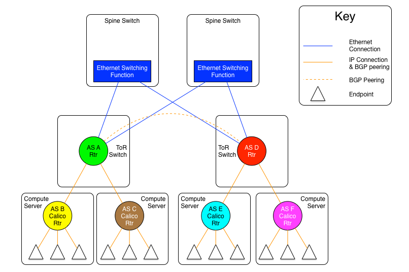
The diagram above shows the AS per compute server model where the ToR switches are physically meshed via a set of Ethernet switching planes.
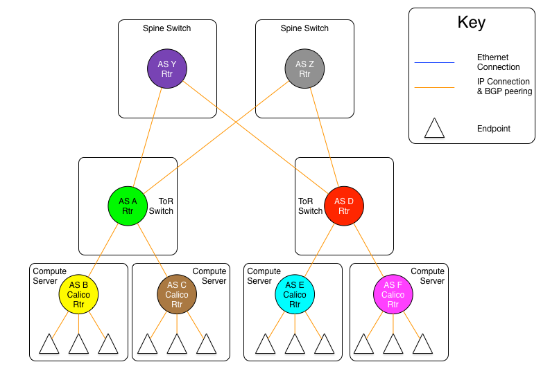
The diagram above shows the AS per compute server model where the ToR switches are physically connected to a set of independent routing planes.
As can be seen in these diagrams, there are still the same two variants as in the AS per rack model, one where the spine switches provide a set of independent Ethernet planes to interconnect the ToR switches, and the other where that is done by a set of independent routers.
The real difference in this model, is that the compute servers as well as the ToR switches are all independent autonomous systems. To make this work at scale, the use of four byte AS numbers as discussed in RFC 4893. Without using four byte AS numbering, the total number of ToRs and compute servers in a Calico fabric would be limited to the approximately five thousand available private AS (note 5) numbers. If four byte AS numbers are used, there are approximately ninety-two million private AS numbers available. This should be sufficient for any given Calico fabric.
The other difference in this model vs. the AS per rack model, is that there are no route reflectors used, as all BGP peerings are eBGP. In this case, each compute server in a given rack peers with its ToR switch which is also acting as an eBGP router. For two servers within the same rack to communicate, they will be routed through the ToR. Therefore, each server will have one peering to each ToR it is connected to, and each ToR will have a peering with each compute server that it is connected to (normally, all the compute servers in the rack).
The inter-ToR connectivity considerations are the same in scale and scope as in the AS per rack model.
The Downward Default model
The final model is a bit different. Whereas, in the previous models, all of the routers in the infrastructure carry full routing tables, and leave their AS paths intact, this model (note 6) removes the AS numbers at each stage of the routing path. This is to prevent routes from other nodes in the network from not being installed due to it coming from the local AS (since they share the source and dest of the route share the same AS).
The following diagram will show the AS relationships in this model.
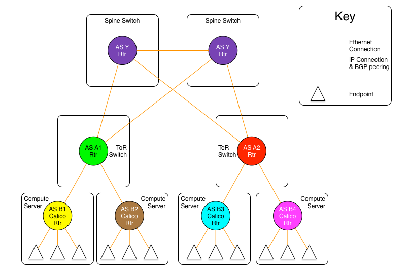
In the diagram above, we are showing that all Calico nodes share the same AS number, as do all ToR switches. However, those ASs are different (A1 is not the same network as A2, even though the both share the same AS number A ).
Although the use of a single AS for all ToR switches, and another for all compute servers simplifies deployment (standardized configuration), the real benefit comes in the offloading of the routing tables in the ToR switches.
In this model, each router announces all of its routes to its upstream peer (the Calico routers to their ToR, the ToRs to the spine switches). However, in return, the upstream router only announces a default route. In this case, a given Calico router only has routes for the endpoints that are locally hosted on it, as well as the default from the ToR. Because the ToR is the only route for the Calico network the rest of the network, this matches reality. The same happens between the ToR switches and the spine. This means that the ToR only has to install the routes that are for endpoints that are hosted on its downstream Calico nodes. Even if we were to host 200 endpoints per Calico node, and stuff 80 Calico nodes in each rack, that would still limit the routing table on the ToR to a maximum of 16,000 entries (well within the capabilities of even the most modest of switches).
Because the default is originated by the Spine (originally) there is no chance for a downward announced route to originate from the recipient's AS, preventing the AS puddling problem.
There is one (minor) drawback to this model, in that all traffic that is destined for an invalid destination (the destination IP does not exist) will be forwarded to the spine switches before they are dropped.
It should also be noted that the spine switches do need to carry all of the Calico network routes, just as they do in the routed spines in the previous examples. In short, this model imposes no more load on the spines than they already would have, and substantially reduces the amount of routing table space used on the ToR switches. It also reduces the number of routes in the Calico nodes, but, as we have discussed before, that is not a concern in most deployments as the amount of memory consumed by a full routing table in Calico is a fraction of the total memory available on a modern compute server.
Recommendation
The Calico team recommends the use of the AS per rack model if the resultant routing table size can be accommodated by the ToR and spine switches, remembering to account for projected growth.
If there is concern about the route table size in the ToR switches, the Calico recommends the Downward Default model.
If there are concerns about both the spine and ToR switch route table capacity, or there is a desire to run a very simple L2 fabric to connect the Calico nodes, then the user should consider the Ethernet fabric as detailed in Calico over Ethernet fabrics.
If you are interested in the AS per compute server, the Calico team would be very interested in discussing the deployment of that model.
Other options
The way the physical and logical connectivity is laid out in this article, and the Ethernet fabric, the next hop router for a given route is always directly connected to the router receiving that route. This makes the need for another protocol to distribute the next hop routes unnecessary.
However, in many (or most) WAN BGP networks, the routers within a given AS may not be directly adjacent. Therefore, a router may receive a route with a next hop address that it is not directly adjacent to. In those cases, an IGP, such as OSPF or IS-IS, is used by the routers within a given AS to determine the path to the BGP next hop route.
There may be Calico architectures where there are similar models where the routers within a given AS are not directly adjacent. In those models, the use of an IGP in Calico may be warranted. The configuration of those protocols are, however, beyond the scope of this technical note.
IP fabric design considerations
AS puddling
The first consideration is that an AS must be kept contiguous. This means that any two nodes in a given AS must be able to communicate without traversing any other AS. If this rule is not observed, the effect is often referred to as AS puddling and the network will not function correctly.
A corollary of that rule is that any two administrative regions that share the same AS number, are in the same AS, even if that was not the desire of the designer. BGP has no way of identifying if an AS is local or foreign other than the AS number. Therefore re-use of an AS number for two networks that are not directly connected, but only connected through another network or AS number will not work without a lot of policy changes to the BGP routers.
Another corollary of that rule is that a BGP router will not propagate a route to a peer if the route has an AS in its path that is the same AS as the peer. This prevents loops from forming in the network. The effect of this prevents two routers in the same AS from transiting another router (either in that AS or not).
Next hop behavior
Another consideration is based on the differences between iBGP and eBGP. BGP operates in two modes, if two routers are BGP peers, but share the same AS number, then they are considered to be in an internal BGP (or iBGP) peering relationship. If they are members of different AS's, then they are in an external or eBGP relationship.
BGP's original design model was that all BGP routers within a given AS would know how to get to one another (via static routes, IGP (note 7) routing protocols, or the like), and that routers in different ASs would not know how to reach one another unless they were directly connected.
Based on that design point, routers in an iBGP peering relationship assume that they do not transit traffic for other iBGP routers in a given AS (i.e. A can communicate with C, and therefore will not need to route through B), and therefore, do not change the next hop attribute in BGP (note 8).
A router with an eBGP peering, on the other hand, assumes that its eBGP peer will not know how to reach the next hop route, and then will substitute its own address in the next hop field. This is often referred to as next hop self.
In the Calico Ethernet fabric model, all of the compute servers (the routers in a Calico network) are directly connected over one or more Ethernet network(s) and therefore are directly reachable. In this case, a router in the Calico network does not need to set next hop self within the Calico fabric.
The models we present in this article ensure that all routes that may traverse a non-Calico router are eBGP routes, and therefore next hop self is automatically set correctly. If a deployment of Calico in an IP interconnect fabric does not satisfy that constraint, then next hop self must be appropriately configured.
Route reflection
As mentioned above, BGP expects that all of the iBGP routers in a network can see (and speak) directly to one another, this is referred to as a BGP full mesh. In small networks this is not a problem, but it does become interesting as the number of routers increases. For example, if you have 99 BGP routers in an AS and wish to add one more, you would have to configure the peering to that new router on each of the 99 existing routers. Not only is this a problem at configuration time, it means that each router is maintaining 100 protocol adjacencies, which can start being a drain on constrained resources in a router. While this might be interesting at 100 routers, it becomes an impossible task with 1000's or 10,000's of routers (the potential size of a Calico network).
Conveniently, large scale/Internet scale networks solved this problem almost 20 years ago by deploying BGP route reflection as described in RFC 1966. This is a technique supported by almost all BGP routers today. In a large network, a number of route reflectors (note 9) are evenly distributed and each iBGProuter is peered with one or more route reflectors (usually 2 or 3). Each route reflector can handle 10's or 100's of route reflector clients (in Calico's case, the compute server), depending on the route reflector being used. Those route reflectors are, in turn, peered with each other. This means that there are an order of magnitude less route reflectors that need to be completely meshed, and each route reflector client is only configured to peer to 2 or 3 route reflectors. This is much easier to manage.
Other route reflector architectures are possible, but those are beyond the scope of this document.
Endpoints
The final consideration is the number of endpoints in a Calico network. In the Ethernet fabric case the number of endpoints is not constrained by the interconnect fabric, as the interconnect fabric does not see the actual endpoints, it only sees the actual vRouters, or compute servers. This is not the case in an IP fabric, however. IP networks forward by using the destination IP address in the packet, which, in Calico's case, is the destination endpoint. That means that the IP fabric nodes (ToR switches and/or spine switches, for example) must know the routes to each endpoint in the network. They learn this by participating as route reflector clients in the BGP mesh, just as the Calico vRouter/compute server does.
However, unlike a compute server which has a relatively unconstrained amount of memory, a physical switch is either memory constrained, or quite expensive. This means that the physical switch has a limit on how many routes it can handle. The current industry standard for modern commodity switches is in the range of 128,000 routes. This means that, without other routing tricks, such as aggregation, a Calico installation that uses an IP fabric will be limited to the routing table size of its constituent network hardware, with a reasonable upper limit today of 128,000 endpoints.
Footnotes
Note 1
In Calico's terminology, an endpoint is an IP address and interface. It could refer to a VM, a container, or even a process bound to an IP address running on a bare metal server.
Note 2
This interconnect fabric provides the connectivity between the Calico (v)Router (in almost all cases, the compute servers) nodes, as well as any other elements in the fabric (e.g. bare metal servers, border routers, and appliances).
Note 3
If there is interest in a discussion of this approach, please let us know. The Calico team could either arrange a discussion, or if there was enough interest, publish a follow-up tech note.
Note 4
However those tools are available if a given Calico instance needs to utilize those policy constructs.
Note 5
The two byte AS space reserves approximately the last five thousand AS numbers for private use. There is no technical reason why other AS numbers could not be used. However the re-use of global scope AS numbers within a private infrastructure is strongly discouraged. The chance for routing system failure or incorrect routing is substantial, and not restricted to the entity that is doing the reuse.
Note 6
We first saw this design in a customer's lab, and thought it innovative enough to share (we asked them first, of course). Similar AS Path Stripping approaches are used in ISP networks, however.
Note 7
An Interior Gateway Protocol is a local routing protocol that does not cross an AS boundary. The primary IGPs in use today are OSPF and IS-IS. While complex iBGP networks still use IGP routing protocols, a data center is normally a fairly simple network, even if it has many routers in it. Therefore, in the data center case, the use of an IGP can often be disposed of.
Note 8
A Next hop is an attribute of a route announced by a routing protocol. In simple terms a route is defined by a target, or the destination that is to be reached, and a next hop, which is the next router in the path to reach that target. There are many other characteristics in a route, but those are well beyond the scope of this post.
Note 9
A route reflector may be a physical router, a software appliance, or simply a BGP daemon. It only processes routing messages, and does not pass actual data plane traffic. However, some route reflectors are co-resident on regular routers that do pass data plane traffic. Although they may sit on one platform, the functions are distinct.